BY : Dr A V Ivanov
DATE : April, 2003
FOR : Demonstration case for v.3.5.0.
TITLE : Lift-generated water vapours condensation over the wings
INTRODUCTION
A Disperse Phase Mass Conservation, DPMC, model application is presented aimed at the demonstration of the method for the simulation of the water vapours condensation effect above the wings of a flying aircraft.
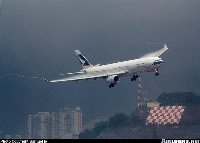
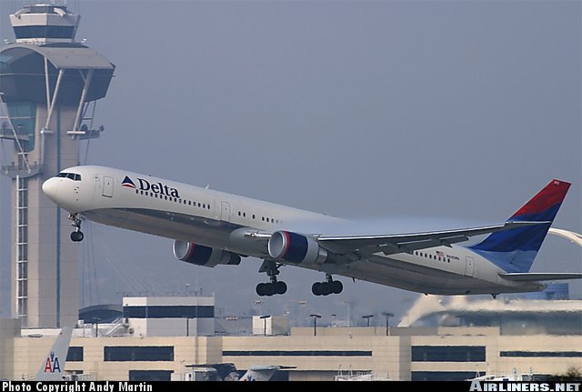
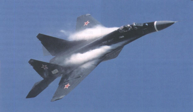
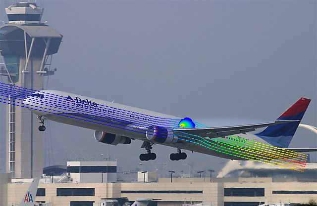
Lifting surfaces such as wings generate condensation in humid air. The lift is due to relatively low air pressure on one side of the wing and relatively high air pressure on the other side. Significant lowering of the air pressure leads to lower the temperature of the air and any water vapours present in the air. If the air pressure on the suction side of the wing is low enough and the ambient air is sufficiently humid, the drop in temperature is enough to cause condensation of water vapours resulting in the formation of a cloud. Clouds form on the upper surfaces of the wings. Such condensation is usually seen during situations requiring large lift, e.g. during high-g maneuvers or during landings or take-offs.
Some examples of lift-generated condensation are pictured below. Because wingtip vortices are also caused by lift, one frequently sees both types of condensation simultaneously.
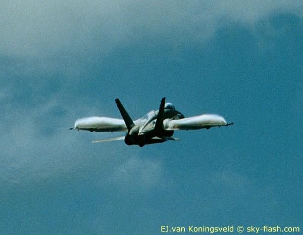
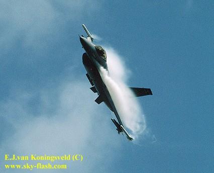
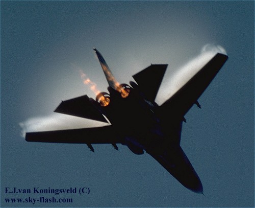
Even more images can be found at Peter Steehouwer's Airshow Image Site, Evert Koningsveld's Sky Flash Aviation Site and at the airliners.net page. Samuel Lo, Andy Martin and Evert J van Koningsveld hold the copyright for above six photos. They are gratefully acknowledged for permission to use these here.
The demonstration case considered consists of a 2D airfoil exposed to the steady uniform external airflow under various attack angles.
Commercial aircrafts were focused on, so appropriate airfoil was adopted.
The airfoil was taken in take-off or landing configuration at which condensation is more pronounced.
It was supposed that approaching flow speed was equal to 100 m/s and constant relative humidity was 80% at ambient temperature 00C.
The task was to predict formation, size and placement of the condensation zone above the wings and also to calculate all related flow field distributions.
In the case presented conjugate heat transfer was carried out to provide detailed information regarding temperature field over the airfoil. The airfoil was treated as solid body filled with aluminum.
It was assumed that difference between humid air temperature and condensed water droplets temperature was very small.
The independent variables of the problem are the two components of Cartesian coordinate system, namely X and Y.
The main dependent (solved for) variables are:
The Chen-Kim modified K-epsilon turbulence model, KECHEN, closed by wall functions was employed to compute the fields of turbulence energy, its dissipation rate and, hence, turbulent viscosity.
Buoyancy source term in the airflow equation was introduced in the case through density-difference option.
No two-phase models were used in the case to simulate water vapours condensation and droplets formation. Instead rather simple Disperse Phase Mass Conservation, DPMC, model was adopted. The main idea of the model which was formulated by L T Matveev [L T Matveev. Course of general meteorology: Physics of the atmosphere. - Leningrad, Gidrometeoizdat, 1976. - 639 p. (in Russian)] is as follows. The liquid water specific humidity, WVL, i.e. quantity of water in liquid state per humid air unit (kg liquid water/kg humid air), is related to the total water specific humidity and �-function which, in turn, solved for variables. �-function is the special conserved variable from which the humid air temperature is deduced.
There are several limitations of DPMC model and it is not applicable for all situations. But condensation of water vapours in the atmosphere it is that case where using of the model is valid and it can be effectively applied.
IN-FORM facility was used to insert necessary formulae and make relevant settings in DPMC model.
The humid air density was computed from the local pressure, humid air temperature and specific humidity.
Saturated specific humidity was set according to the Clausius-Clapeyron equation.
The airfoil geometry was taken from PHOENICS library case Y115.
A "cut-off" technique, PARSOL, for the representation of the complex airfoil shape on the Cartesian grid was used.
The computational domain dimensions were 17.0×10.0 m. The basic grid was nonuniform one and it had in total 5335 cells (97 cells in horizontal direction and 55 cells in the vertical direction).
The plots show the distribution of the liquid water specific humidity, pressure, velocities, humid air temperature and the other related fields over the wing.
Pictures are as follows:
Angle of attack is 01 degreeTreatment of the airfoil as an anonymous solid body proved to be far from satisfactory one because of considerable overheating of the boundary layer around the airfoil. In fact the humid air temperature increase in the thin layer adjoined the airfoil was unlimited. For this reason the solution procedure diverged. Overheating is likely to be accounted for PHOENICS built-in heat source which includes the viscous dissipation of heat. To avoid these problems the airfoil was filled with aluminum and conjugate heat transfer was considered. As a result overheating was eliminated (due to heat sink into the airfoil) and convergence was achieved.
Consideration of the real internal structure of the airfoil, although in simplified manner and still in 2D, including holes filled with fuel and the warm air of the wing anti-ice system can be of service and promising for the next stages of the lift-generated condensation study.
In the next stages of above mentioned study the following items can be concerned:
It was found that IN-FORM and Fine Grid Embedding method (FGEM) cannot work simultaneously in the case. So FGEM option was cancelled.
Using of the special parameter, SARAH, promoted convergence of the solution procedure.
All model settings have been made in VR-Editor of PHOENICS v.3.5.0.
Prof. B S Mastryukov and Dr S V Zhubrin are gratefully acknowledged. Prof. B S Mastryukov for the long-term scientific supervising and Dr S V Zhubrin for the special attention to the author on initial stages of author's activity as a PHOENICS user.